KONTAKT
Innovation Garage, Skovlunde
Skovlunde Byvej 96A
DK-2740 Skovlunde
Niels Døssing Overheu
Region Hovedstaden
T: 38665563
E: niels.doessing.overheu@regionh.dk
Site owner:
Capital Region of Denmark
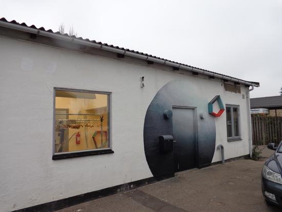
Former dry cleaning facility
PCE in clay till and sand aquifer, P&T plant
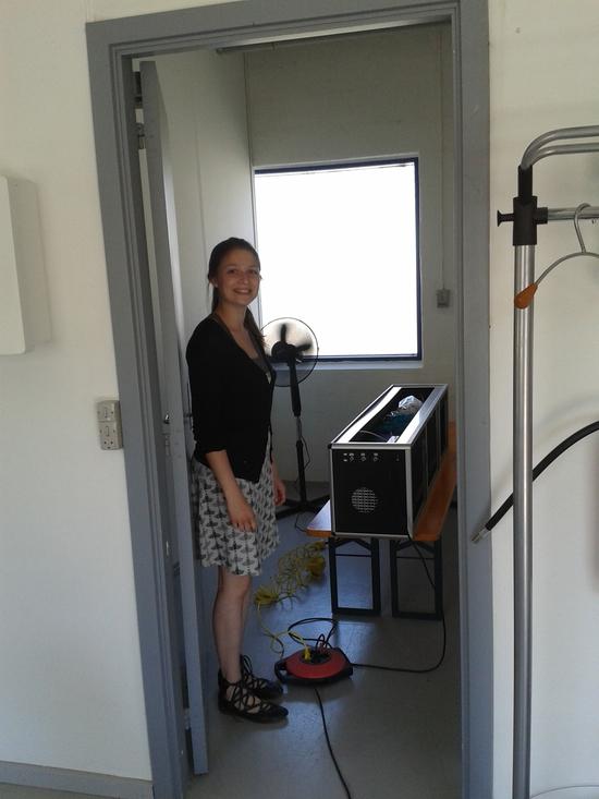
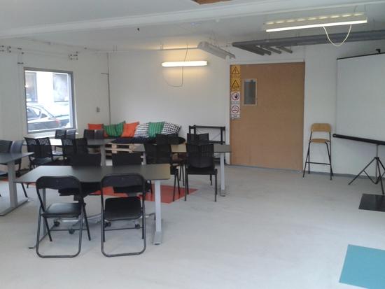
Meeting room and office spaces.
Præsentation af sitet
The site is a former dry cleaning facility heavily contaminated with chlorinated solvents, which was prioritized for an expensive publicly financed remediation. In 2012 the Region saw the opportunity to purchase the site in order to test more cost-effective and sustainable remediation methods without annoying a site owner. In this way, the region hoped to reduce the overall cost of remediating the site while also building up knowledge. Furthermore the buildings at the site could be used for meetings and workshops.
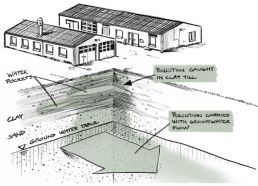
Below the fill is 6-8 meters of clay till. The first about three meters of till is soft and moist with sand lenses, while the lower part is compact and dry.
About nine m bgs is a layer of fine, silty sand which continues to about 20 m bgs. The sand layer is unsaturated in the upper five meters. In the deepest well in the area (27 m bgs) the sandy deposits get coarser with depth and are characterized as coarse gravel in the bottom.
The limestone deposits are expected to be found about 27 m bgs, however no boreholes in the vicinity reach the limestone.
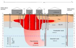
Operation of dry cleaning facilities from 1960-1987 has caused has caused heavy contamination with chlorinated solvents, mainly tetrachloroethylene (PCE). About 2 tons of PCE is expected at the site. In the hot spot below the northern building, high concentrations have been found as far down as 8.5 m bgs, while the overall picture outside the hot spot is vertical diffusion from 2.5 to 4 m bgs.
PCE is by far the most dominant component in the soil. Only small and insignificant quantities of decomposition products, hydrocarbons and BTEX have been found in the soil, compared to the PCE concentrations.
In the secondary groundwater in the clay till from 2–5 m bgs, extensive contamination by PCE, TCE, decomposition components and hydrocarbons have been found.
One well screened in the regional sand aquifer below the till is also contaminated, and high concentrations of degradation products are detected compared to PCE (well no. B203). The high content of decomposition components in relation to PCE in the groundwater is considered evidence of a high degree of natural decomposition in the unsaturated and saturated zone. In 2012 a pumping well screened in the regional sand aquifer was drilled in order to maintain hydraulic control of the leaching contamination during the site’s lifetime as a test site (well no. 200. 6903).
The figures below show a simplified 3D conceptual site model and a north-south cross-section through the hot spot area. More site information and cross-sections (in Danish) can be found in the collection of Technical documents.
Beskrivelse
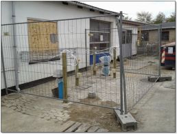
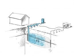
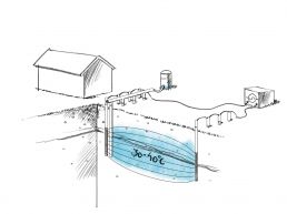
Pilot scale test of using freezing processes to speed up transport of degradation products through tight soils.
In Spring 2018 freezing tests are conducted at an uncontaminated site, while hydraulic testing is carried out at the Innovation Garage to see if the site is fit for pilot scale tests on contaminated soil.
The project is funded by the Danish Innovation Fund and the partners below.
Project was terminated prematurely because objectives could not be met.
Projektdokumenter
Beskrivelse
The purpose of this project has been to determine and document a suitable procedure for future measurements of the air pressure gradient between the air pressure under a concrete floor and the air pressure inside a building. As a part of this procedure, the most significant parameters that determine the pressure gradient have been identified and additional measurements to support pressure gradient measurements have been proposed.
Published as Danish EPA project no. 1896, 2016.
Projektdokumenter
Beskrivelse
Challenge and Solution
Spills of chlorinated solvents are a main concern of the Capital Region of Denmark, since they threaten the groundwater resources we use for drinking water.
Once the chlorinated solvents reach the groundwater aquifers, they are difficult to treat effectively. Pump-and-treat systems are commonly used, but these are long-term solutions with substantial operation and maintenance costs. So the Capital Region is involved in development of methods that can treat the groundwater in the aquifers without the need to pump water to the surface.
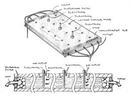
One possible solution is to clean contaminated groundwater using electricity, since electric current can create reactants that degrade the contamination to harmless substances in the aquifer. In an industrial PhD-project, a groundwater aquifer is simulated to test if electrochemical remediation is a solution to our challenges. If successful, we will try out the method in the ground.
Brief Technical Details
An electrochemical zone for in situ degradation of chlorinated solvents may be a viable alternative to pump-and-treat. Near the electrodes we can obtain fast electrochemical reduction of chlorinated solvents and we may also be able to generate reactants, which bacteria can subsequently use in biodegradation processes.
The focus is on intelligent use and combination of the different electrochemical processes to optimize the zone for chemical and biological degradation of the chlorinated solvents. Experimental work in a 1D soil column and a 2D sand box will be conducted on both sand and limestone to reflect natural Danish groundwater reservoir geologies before advancing the technology to in situ testing.
Occupies Room 4.
Beskrivelse
Projektdokumenter
Beskrivelse
EU Horizon 2020 International Training Network with the purpose of training 14 PhD-students in producing, testing and injecting metal-oxides for subsurface contaminant removal and immobilization.
For more information, see
Beskrivelse
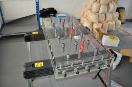
Development and test of optical sensor for real time measurement of volatile organic contaminants in air
Projektdokumenter
Beskrivelse
Beskrivelse
Column tests to study the feasibility of creating precipitated geological membranes in the subsurface to limit evaporation of harmful vapors to indoor air.
The tests were promising, but the vapor inhibiting effects have been shown to relapse toward the original conditions over time.
The details are published in the report below (in Danish).
Projektdokumenter
Beskrivelse
Text and references from poster material...
Beskrivelse
The passive tracer gas technology called PerFlourcarbon Tracer (PFT) has been tested for estimating site specific attenuation factors between sub-slab soil gas and indoor air at sites with slab on grade. As a part of the study, the installation procedure and the speed of diffusive tracer gas migration in the sub surface has been investigated.
With regard to the installation procedure and choice of materials for installing the tracer gas sources directly under the concrete slab (after core-drilling through the slab), satisfying results have been obtained. Hence, the developed installation procedure has been proven not to open up new preferential migration pathways through the concrete slab. The procedure can be used when a high quality seal is desired, after performing environmental investigations, where perforation of the concrete slab is involved.
Unfortunately, we did not succeed in our efforts to propose and document a method that can be used for estimating site specific attenuation factors between sub-slab soil gas and indoor air at sites with slab on grade. We do, however, think that there is a basis for establishment of a procedure/methodology that will enable estimation of site specific attenuation factors at sites with more permeable sub-slab soil types or at sites with a capillary barrier layer of e.g. Leca® or with a layer of insulation material. At such sites it will be much easier to ensure a satisfactory sub-slab distribution of the tracer gas.
Published as Danish EPA project no. 1898, 2016.
Projektdokumenter
Praktisk
How to get there and where to park:
Please consult these directions.
Entering the buildings:
The buildings are accessed using a control panel at the main door of the northern building. Inside the door to the left you will find a set of keys to the rest of the entrance doors. Please return the keys to their place before you leave.
Capital Region employees: You can use your chip tag to open the main door just like your regular office.
External partners: Contact the site administrator or our technician Kim Larsen (+45 2033 4722) to get a code, a chip tag or have the door unlocked remotely.
How to book test space and meeting rooms:
Capital Region employees: Send an Outlook meeting request to CRU-FP-Testgrund specifying the space requested, the activity and the expected noise level. See room numbers in Infrastructure for testing below. The booking is confirmed when the administrator accepts the request.
External partners: Talk to your Capital Region contact or the site administrator to make the booking.
Heavy vehicles:
Generally the access conditions for heavy vehicles are good. If any cars are in the way between Skovlunde Byvej and the site, please contact the site administrator or talk to the nice people at Palms Auto (our neighbors to the south). The free space between our two buildings is five meters.
Two toilets
One with shower.
The toilets are located in the western end of the northern building.
Extra tissue can be found in the storeroom by the kitchen.
Kitchen
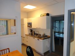
Fitted with dishwasher, oven, two hot plates, coffee machine, kettle, fridge/freezer and tableware for about 20.
You are welcome to brew the coffee and tea found in the cabinet. All other food and drinks (besides water) must be brought by yourselves.
Meeting room
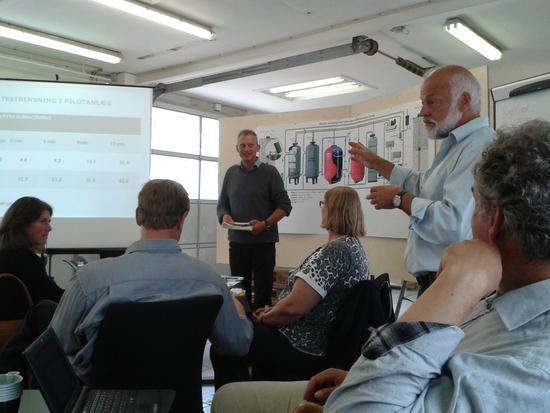
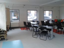
Easily fits 25, with a little effort up to 40. The meeting room has a screen, projector and several bulletin boards.
Office
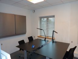
Fits 2-4 people.
Internet
The region’s network is available for wired (northern building) and wireless access (both buildings). Non-region devices can use our open guest network “RegHGaest”. Open an internet browser, type your e-mail address, and log on.
Printer / scanner
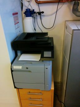
There is a network printer in the kitchen. Capital Region PCs can access the printer as STB-RGH-CRU14. External partners can print using the black USB cable hanging behind the printer. Note that the sliders in the paper tray are a little sensitive, so if it complains about wrong paper type, try adjusting the paper tray sliders back to A4 format. The machine can also scan to pdf-format and send the files by e-mail.
Rooms and facilities:
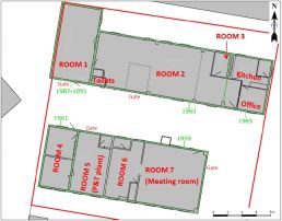
The site offers several rooms with space and utilities for testing purposes. Please see room numbers in the figure below. Photos of the rooms can be found in the Photos collection.
There are plenty of regular grounded 220V outlets, two 400 V/16 A CEE outlets in Room 2, one 400 V/16 A CEE outlet in Room 7 and several old type 380 V/16 A outlets in Room 4 and 5 and one in Room 7. If more specific outlets are needed, let us talk about it.
Gate dimensions:
Room 1: Height x Width: To be measured
Room 2: Height x Width: 2.65 x 2.95 m
Room 5: Height x Width: 2.50 x 2.70 m
Room 7: Height x Width: 2.60 x 3.30 m
For available space at a given time, please have a look at the site calendar or contact the site administrator.
Groundwater:
Monitoring wells:
There are five wells at the site, which are suitable for sampling and measuring water levels. They are all screened in the secondary sandy aquifer, cf. the section on Geology. For further information, please see the document on the location and construction of the monitoring wells.
Pump and treat plant:
The contamination leaching from the site is hydraulically fixed by pumping contaminated water from the underlying sandy aquifer from a well just south of Room 5. The water is treated in a state-of-art traditional pump-and-treat (P&T) plant constructed in 2012. The plant is fitted with two serial aerated sand filters to remove iron and manganese and two serial reactors containing granular activated carbon (GAC) to remove the chlorinated organic contaminants. The sand filters are automatically backwashed once a day to remove metal precipitates.

The flow through the plant is quite stable between 1.6-1.8 m3/h. The pressure before sand filters generally varies between 0.1-0.2 bars and before the GAC reactors between 0.02-0.05 bars.
Concentrations of chlorinated solvents in the abstracted water has decreased from several hundred µg/l of individual compounds to less than 100 µg/l combined. During 2015 the following general concentration levels were registered:
- PCE: 35-70 µg/l
- TCE: 15-30 µg/l
- cis-DCE: 15 µg/l
- VC: 0.15 µg/l
Concentrations of iron and manganese in the inlet vary around 4 mg/l and 0.15 mg/l respectively, which is effectively removed in the sand filters. The most recent analysis report on geochemical parameters is found here. Sampling point P1 is inlet and P10 is outlet.
Location of sampling points on the P&T plant can be found in the data sheet for the plant.
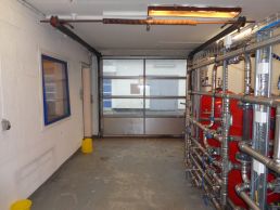
It is possible to divert a part of the contaminated water from the P&T plant to conduct tests on water remediation. Three valves are installed which makes it possible to divert a stream either before sand filtration or before the GAC reactors and lead the diverted stream back for final polishing in the GAC reactors. Alle valves are manual ball valves with 2" inside threaded steel pipes, see picture below. There is easy access to space for testing new equipment either next to the P&T plant or in Room 4. With some extra piping, space can be used in the other rooms as well.
Soil:
There are generally high concentrations of PCE from very close to terrain to about 8 m bgs. in the area under the western part of the northern building and the western part of the space between the buildings. The highest concentrations are found 3-5 m bgs.
TCE content is generally less than 5% of the chlorinated compounds, but there are variations. Degradation products constitute about 0,5% of the mass.
Please consult the plan view of soil concentrations, the cross sections and additional info on soil contamination in chapter 3 in the 2011 report (in Danish).
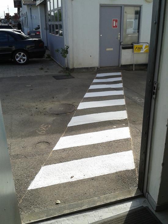
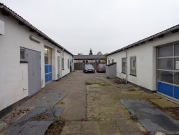
The area between the buildings is very accessible for soil sampling due to limited paving (see photo below) and contamination from less than half a meter below the surface.
Air:
Soil air:
The soil air is contaminated by PCE and TCE all across the site. The highest concentrations are found at the hot spot under the western end of the northern building. We currently have two data sets of sub-slab concentrations:
- A comprehensive investigation across the site from 2005
- An investigation in the southern building from 2014
We advise using the 2005-data for the northern building and the 2014-data for the southern building until a new comprehensive investigation has been performed. Specifically, the 2005-data for the southern building cannot be used, since a thermal remediation method was pilot tested under Room 7 (southern building) in 2013.
Floor construction:
A comprehensive examination of the construction details of both buildings was carried out in 2014. Please consult the examination report (in Danish) for details on the construction of the floors and other building parts as well as expected contaminant migration pathways.
Please note: The examination report mentions two large trenches cut through the concrete floor of Room 2. Both of these were repaired in 2015 in an effort to reduce indoor air contaminant concentrations. As indicated in the section below, these efforts were not succesful.
Indoor air:
Indoor air concentrations have been measured several times using ORSA-tubes, most frequently in the northern building. Efforts have been made to reduce indoor air concentrations in the kitchen and office section and since late 2015, two "Molly" air purifying units have been in place to keep concentrations low in that section. New measurement rounds are planned for 2016. Other projects to test indoor air remediation are very welcome.
Current documents on indoor air:
- A report on concentration development in the northern building and Room 7 (2015). The report illustrates the (lack of) effect of repairing the floor in Room 2 in 2015 and testing indoor air remediation in the kitchen and office section in 2015. Please note: Measurement point IL10 is not shown on the map in the report. IL10 is located in Room 7 in the south building.
- Results of indoor air concentration measurements in both buildings (Aug. 2014).
We advise using the 2015-data for the northern building and Room 7 and the 2014-data for the southern building (excl. Room 7) until a new comprehensive investigation has been performed.
Other infrastructure:
Heat pump:
The site is a demonstration facility to evaluate the potential of exploiting the extracted groundwater in the P&T plant for heating and cooling purposes. The P&T plant is fitted with a heat exchanger connected to a heat pump which extracts 3-5 degrees C from the groundwater which is used for room heating. Furthermore, an airconditioning unit in Room 6 uses the groundwater as a coolant. Combined heating and cooling increases the efficiency of the heat pump. In late 2015/early 2016 the region evaluates the efficiency of the heat pump. Please contact the site administrator for further info.
Solar panels:
The site is also a demonstration site to evaluate the potential of using solar panels to supply the P&T plant with electricity. Solar panels were established on the roof of the northen building in early 2015. We will evaluate the efficiency of the solar panels in 2016. Please contact the site administrator for further info.
- Analysis - Well control parameters (boringskontrol) 04.02.2016
- Conceptual cross-sections (2011)
- Conceptual site model (geology, soil and groundwater) 2018
- Construction examination (2014)
- Data compilation report 2017
- Data sheet for P&T plant
- Directions to the Innovation Garage
- Indoor air - 2015 report
- Indoor air - Aug. 2014 measurements
- Indoor air concentrations and filtration tests 2017
- Piping and Instrumentation (PI) diagram and well drawings
- Report 1998a Jan. - Investigation
- Report 1998b Apr. - Supplementary investigation phase I
- Report 1998c Oct. - Supplementary investigation phase 2
- Report 1998d Dec. - Remediation project proposal
- Report 2000 - Remediation project - Drain and excavation
- Report 2006 - Appendix figures
- Report 2006 - Supplementary investigation and reassessment of remediation facility
- Report 2011 - Investigation
- Report 2015 - P&T plant documentation and operation
- Soil air conc. and ventilation test North building 2017
- Soil air concentrations (plan view) 2005
- Soil air concentrations (south building, plan view) 2014
- Soil concentrations (plan view) 2005
- Stratigraphy and screens - Monitoring wells 2021
- Stratigraphy and screens - Pumping and infiltration well
- Third party agreement template
Visitors:
Generally we ask that you treat the facilities with respect and clean up after yourselves. This includes tidying the kitchen and emptying the dishwasher when it is done. Turning off the lights and locking the doors when you leave. You know the drill. We have service personnel to empty the waste bins and routinely clean the toilets and floors.
Project owners:
If you wish to use the facilities to test a method “on your own” (i.e. the region is not involved in the test), you are welcome to do so. We ask you to sign an agreement, which commits the project owner to take responsibility for any damages under Danish law and for not increasing the cost of future public efforts to remediate the contamination. Here you can find a template for the agreement.
Igangværende projekter
Beskrivelse
Contaminated building materials: Testing of methods for estimating contaminant content in building materials and flux from these to the indoor air.
Effective Sub-slab depressurization: Testing the robustness of a sub-slab depressurization system in mitigating vapor transport across the concrete floor, via cavity walls and sewers.
Beskrivelse
Heat pump:
The Innovation Garage has a demonstration facility to evaluate the potential of exploiting the extracted groundwater in the P&T plant for heating and cooling purposes. The P&T plant is fitted with a heat exchanger connected to a heat pump which extracts 3-5 degrees C from the groundwater which is used for room heating. Furthermore, an airconditioning unit in Room 6 uses the groundwater as a coolant. Combined heating and cooling increases the efficiency of the heat pump.
Contact: Line Mørkebjerg Fischer.
Aquifer Thermal Energy Storage (ATES):
A project group based in the Operation & Maintenance team explore the possibilites of using P&T plants for ATES.
Contact: Anne Mette Granhøj Hansen

